Saturday, July 20, 2013

Hillbilly Tracking of Low Earth Orbit Satellites

An adventure of the Southern Appalachian Space Agency,
by Travis Goodspeed <travis at radiantmachines.com>,
as presented at Summercon 2013,
inspired by the lectures of Adam Laurie and Jim Geovedi,
with kind assistance from Skytee.

SASA

At Black Hat DC in 2008, I watched Adam Laurie present a tool for mapping Ku-band satellite downlinks, which he has since rewritten as Satmap. His technique involves using an DVB-S card in a Linux computer as a receiver through a 90cm Ku-band dish with fixed elevation and a DiSEqC motor for azimuth motion. It was among the most inspirational talks I'd ever seen, and I had a blast recreating his setup and scanning the friendly skies. However, such a rig is limited to geostationary satellites in a small region of the sky; I wanted to see the whole sky, especially the moving targets.

In this article, I'll demonstrate a method for modifying a naval telecommunications dish to track moving targets in the sky, such as those in Low Earth Orbit. My dish happily sits in Tennessee, while I direct it using my laptop or cellphone here in Europe. It can also run unattended, tracking moving targets and looking for downlink channels.

The Hardware

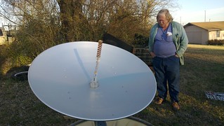
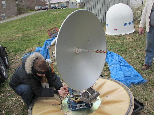
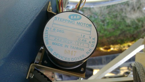
This is my dish, originally a Felcom 82B from Furuno, intended as a mobile earth station on maritime vessels. It would connect to one of the Inmarsat satellites in geostationary orbit, using mechanical gyroscopes to correct the dish against the ship's movements. My use case is the opposite, trying to track moving targets from a stationary ground position.

SASA

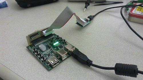
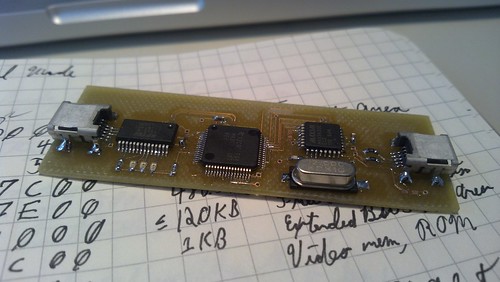
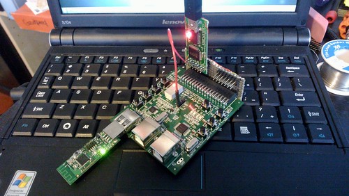
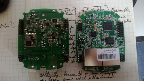
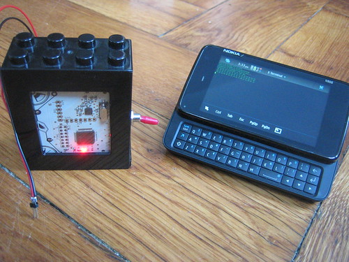
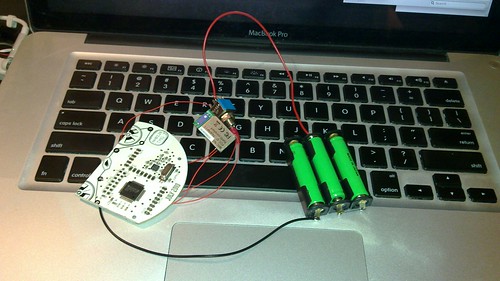
The first of several modifications was to place the motors under computer control. Rather than build dedicated electronics, I took the lazy route and wired an EiBotBoard into a BeagleBone for motor control. I wired things such that the first motor is Azimuth and the second motor is Elevation, with the Tilt motor disabled.

Stepper Motor EAD ZA23ECK-12T1

20130322_012

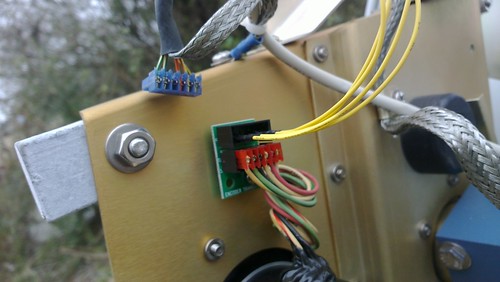
When testing the stepper motors, I found it handy to have a second EBB that was wired into standalone motors, so that my control software could run away from the dish. The EBB appears to its host computer as /dev/ttyACM0, and it's easy to test the motors by directly sending commands. To move both motors slowly forward 400 steps for three seconds, run echo "SM,3000,400,400" >>/dev/ttyACM0 on the BeagleBone. To do this from software, a control application can simply open /dev/ttyACM0 as a file and write the relevant commands into it.

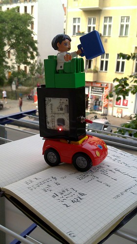
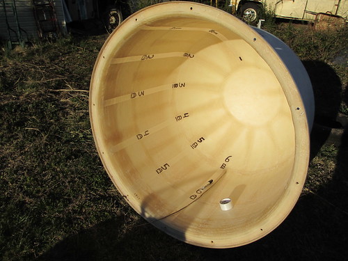
In case the Azimuth or Elevation become lost, I really don't want to travel for two days just to lift the radome and recalibrate. For that reason, we painted the twelve hours of a clock inside of the radome and added a webcam. When lit by the Sun, the camera can be directed to twelve o'clock in order to ensure the dish itself is pointed nearly South. Finer calibration is performed by radio against geostationary targets.

SASA

Southern Appalachian Space Agency

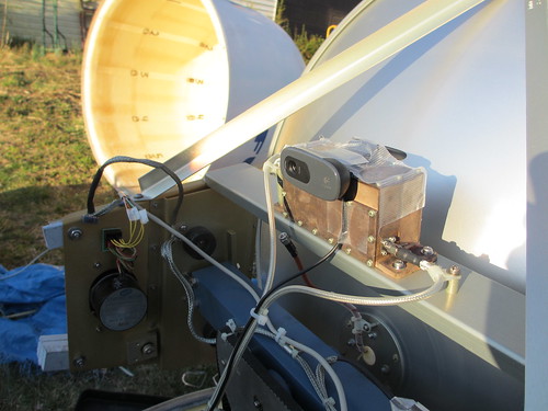
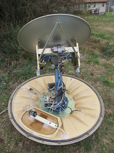
For handling the radio input and controlling the motors, I have a BeagleBone wired into a USB hub. These are all mounted on the trunk of the assembly inside of the radome, sending data back to a server indoors. Unfortunately, I couldn't fit everything over the assembly's original ring connector, so an umbilical cord connects the dish to the outside world. To prevent this cord from tangling, software prevents the dish from spinning more than 360 degrees in azimuth.

Southern Appalachian Space Agency

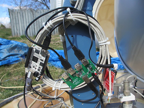
Additionally, I wanted input from an Inertial Measurement Unit. While definitely a luxury rather than a necessity, this allows for direct measurement of the dish's elevation. In future rebuilds, I'll use a much cheaper accelerometer. The unit I chose was a VectorNav VN100, as its UART output could run directly to the BeagleBone without requiring another USB port.

The Daemons

In order to operate the dish, I wanted both a flashy GUI and concise scripting, but scripting was the higher priority. Toward that end, I constructed the software as a series of daemons that communicate through a PostgreSQL database on a server inside the house. For example, I can run SELECT * FROM sats WHERE el>0 to select the names and positions of all currently tracked satellites that are above the horizon. To begin tracking the International Space Station if it is in view, I run UPDATE target SET name='ISS';.

These daemons run on two machines, with everything computationally intensive on an AMD64 server and everything that needs to be locally within the radome on a BeagleBone.

For predicting satellite locations, I wrote a quick daemon using PyEphem that fetches satellite catalog data from CelesTrak. These positions are held in a database, with duplicates filtered out and positions constantly updated. PyEphem is sophisticated enough to predict in any number of formats, so it's easy to track many of the brighter stars as well as planets and deep-space probes, such as Voyagers 1 and 2.

In addition to knowing where the satellites are, it's also necessary to know where the dish is and how the dish is tilted. For this, I have one daemon to watch my IMU's input and a second daemon to control the motor. These two are both used to predict the position, as the motor daemon does dead reckoning to compare against the IMU daemon's values.

Finally, there are a few different daemons and clients for directing the targeting of the dish. Generally, I run one slow background process to retarget every fifteen minutes, so that I can take manual control of the dish using a GUI application.

The GUI

Once the daemons were running smoothly, I tossed together a GUI using Pygame and the same database library that the daemons use. The GUI is operated by keyboard and mouse commands, with a left-click targeting an object and a right-click targeting a position. Named stars can optionally be shown in the background and moving targets are tracked as they move.

SASA Commander, Polar View

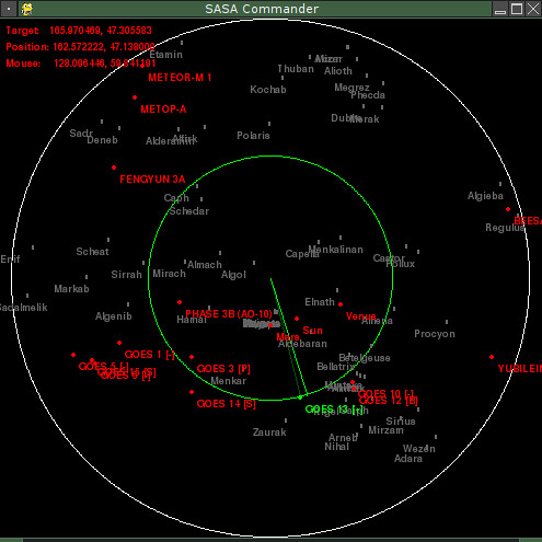
In the screenshot above, the dish is aimed at GOES 3 and has just been ordered to aim at Voyager 1. Future enhancements to the GUI will show radial views and offer some control or visualization of the radio data.

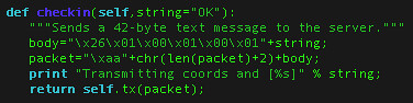
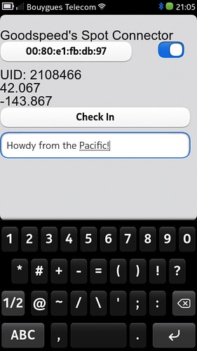
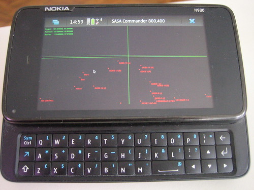
Being written in Pygame, I can run the same exact code on both my laptop and my phones. Coding new features while bored on the Ubahn is a lot healthier than Angry Birds or Sudoku.

SASA Commander on the N900

The Radio

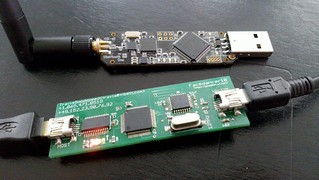
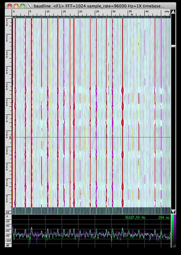
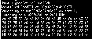
My initial build using an RTLSDR dongle. Data processing is done on my server, with the BeagleBone forwarding data from rtl_tcp. To avoid offending the FCC and ham radio operators everywhere, I disabled the dish's 1.5GHz transmitter and use only the 1.6GHz downlink antenna. If I can justify the extra weight, I'd like to drop the RTLSDR in favor of a USRP2 over Gigabit Ethernet in order to get greater bandwidth and sensitivity.

Recordings are stored either as raw I/Q data or as a simple signal strength indicator from the Power Spectral Density (PSD) function. In the near future, I hope to automatically adjust the aim of the dish in realtime based upon the signal quality feedback.

Next Steps

When time and travel allow, I plan to replace the old Low Noise Amplifier (LNA) with one that has wider bandwidth. I'm also hoping to add support for new radio bands either by swappable antennas or by adding more antennas to the collection.

Thank you kindly.

As a final note, I'd like to thank Skytee for trekking six timezones to help me out with this. Thanks are also due to my next-door neighbors for not panicking when they thought I was talking to aliens.

L Band

Tuesday, October 9, 2012

Emulating USB DFU to Capture Firmware

by Travis Goodspeed <travis at radiantmachines.com>,
to be presented at Breakpoint Melbourne 2012,
continuing Emulating USB Devices with Python,
with thanks Sergey Bratus and the Dartmouth Scooby Crew.

Ever since breaking the MSP430's UART BSL back in '07, I've loved attacking bootloaders, particularly those in Masked ROM. A good bootloader exploit exposes the firmware of anything using that chip, drastically reducing the amount of work I need to do on a given target. As an alternative when a bootloader exploit isn't available, I've found it handy to reverse engineer firmware updater applications to get firmware images.

Toward that end, I'm happy to announce that USB Device Firmware Update emulation is working on the Facedancer Board, so you can emulate DFU devices in order to catch firmware updates as they are sent from a USB host. In many cases, this will require a bit of patching for your specific target, but it's damned handy when you haven't got the time to reverse engineer a firmware updater.

Facedancer is an Ubertooth

In this brief article, I will explain how the Device Firmware Update (DFU) protocol works under the hood, by walking you through the one that I wrote for the Facedancer hardware. As an example target, we will be catching the firmware update for one of Mike Ossmann's Project Ubertooth boards by emulating one well enough to fool the ubertooth-dfu tool that Jared Boone has contributed to that project.

A Child's Guide to USB Device Firmware Updates, Suitable for Adults

USB DFU is a protocol for reflashing devices. By recording and replaying such an update, it is possible to port a firmware update utility to a second operating system, to patch a device's firmware, or to extract a copy of firmware for reverse engineering. If none of these things interest you, feel free to stop reading.

First and foremost, you should understand that the DFU mode is usually a secondary function of a USB device. In emulating such a device, you might need to emulate enough of its legitimate protocol that the host believes that (1) the device is the device that it intends to reprogram and that (2) the device's firmware is out of date and needs to be replaced. Exceptions include devices with a DFU recovery mode.

Second, you should know that the host might attempt to read back from the device, such as to verify that an erasure was successful. As every dialect of DFU seems to do this slightly differently, you might need to patch your implementation to support such features.

Facedancing as USB DFU

The Facedancer acts as a minimal USB Device Firmware Update emulator with the goodfet.maxusbdfu client. Typically, the command needs to be told which style of chip to emulate, where to save the output, and, optionally, what to use as the prior firmware for read attempts.

To emulate a typical victim with your Facedancer, just run 'goodfet.maxusbdfu foo bar' where foo is the hexadecimal Vendor ID and bar is the Product ID. Then plug the Victim end of your Facedancer into the target machine and order a firmware update, the blocks of which will be printed as hex to stdout.

First, we need to know the Vendor ID and Product ID of our target. These are given for the default firmware by 'lsusb' as FFFF:0004. If you are lucky, most commonly with low-volume devices, you'll find a VID/PID pair that comes from the chip manufacturer, such as 0483:DF11 for an STM32. Sometimes the device enumerates differently for DFU than for general use, so expect surprises here.

The default USB listing for the Ubertooth is below. Note that by default it doesn't show any DFU support. Support only appears when the device is put into flashing mode with 'ubertooth-util -f'.

Ubertooth lsusb

When switched into DFU mode, the device changes its USB device descriptor to indicate DFU support. Be sure to remember this when reverse engineering your own devices, as they might support DFU but not advertise it.

Ubertooth in DFU Mode

A Tourist's Phrasebook for DFU

In order to read the goodfet.maxusbdfu source code, it's handy to know at least the basics of the protocol. In this section, I'll give you an informal description of it.

DFU consists of SETUP queries, which have a standard set of header parameters. Some chips implement extra commands, particularly when they have too large an address space for the limited offsets allowed by the UPLOAD (2) and DNLOAD (1) commands. Generally, the bmRequestType will be 0xA1 and the bRequest will be one of the following.

bRequestwValuewIndexwLength
0x00 DETACH
0x01 DNLOADblocknumblocklen
0x02 UPLOAD
0x03 GETSTATUS0x0006
0x04 CLRSTATUS
0x05 GETSTATE0x0001
0x06 ABORT

The GETSTATE (0x05) command will often come first. The ten status from the Bluetooth's DFU client are as follows, but you can often get by with always returning the dfuIDLE (0x02) response. GETSTATE always wants a single byte as its reply, and as with the other DFU commands, all of this runs over the Setup endpoint as a Class request.

#From the ubertooth-dfu source code.
0: 'appIDLE'
1: 'appDETACH'
2: 'dfuIDLE'
3: 'dfuDNLOAD_SYNC'
4: 'dfuDNBUSY'
5: 'dfuDNLOAD_IDLE'
6: 'dfuMANIFEST_SYNC'
7: 'dfuMANIFEST'
8: 'dfuMANIFEST_WAIT_RESET'
9: 'dfuUPLOAD_IDLE'
10: 'dfuERROR'

Additionally, you'll need to support GETSTATUS (0x03) to let the host know the UPLOAD and DNLOAD requests have completed successfully. This one is really easy, just return six bytes of zeroes in response to any request.

The DNLOAD (0x01), like all others, is over Endpoint 0. Its data payload consists of the data to be written, but the address gets to be a bit complicated. Rather than give an absolute address, DFU clients merely provide a 16-bit block number in the wValue field of the Setup request. On the Ubertooth's NXP LPC1756 chip, the address is simply the base address of flash memory plus 256 times the block number. Other chips, such as the STM32, have an extra command that specifies the base address, but these commands are non-standard and will need to be implemented specific to the device.

Recap and Basic Usage

If you've followed along so far, don't worry about being a little lost. Let's step back a bit and actually capture a firmware image, using the default script. In the next section, we'll get back to the nuts and bolts in order to capture a slightly trickier update.

In one window, start the DFU emulator on your Facedancer with 'board=facedancer11 goodfet.maxusbdfu ffff 0004'. You'll see the device warm up and then appear on lsusb listings of the victim machine.

Finally, send a DFU update to our fake Ubertooth board by running 'sudo ./ubertooth-dfu --write bluetooth_rxtx.dfu'. You should see packets scroll across the screen that look like the ones below. Pipe them to a file and you'll have a record of everything that would've been written into the device, enough to make a patch or begin reverse engineering with IDA.

Facedancer DFU Emulator

Complications of Entering DFU Mode

Thus far, we've been emulating a device that is *already* in DFU mode, but in the real world, few devices ship that way.

For example, the following is an error message caused by using the naive DFU emulator script presented earlier with a VID:PID of 1d50:6000. The update script is failing because it orders the USB device to enter DFU mode, but the Facedancer doesn't know how to respond. When emulating closed-source devices, you'll run into the same issue.

Failure Entering DFU

In order to patch this issue, I looked at the emulator's log to see that it blindly accepted a vendor request without knowing what to do.

Unhandled Vendor Request in
USB

On a real Ubertooth device which appears as 1d50:6002, command 19 causes the board to disconnect and launch the DFU application, after which it reappears as ffff:0004. On more complicated devices, you might need to reply with a version number less than the one you wish to receive.

On many devices, such as those newfangled iPods and iPhones, a DFU recovery mode can be entered by holding a particular key combination. To emulate those devices, just hold the key combo and use lsusb to find the right settings for your Facedancer.

Complications of Non-Standard Extensions

If you've dealt with bootloaders before, you'll notice that quite a bit is missing from the DFU protocol as I've described it here. There's been no mention of any way to write to an address except by its block number, nor any mention of commands to erase the device or to enable protective modes. That's because these features are not standard; they are implemented differently for every host.

The STM32, for example, implements special features as writes to block 0000. If you see `BLOCK 0000 : 41' in your log, that means that the host has ordered the device to erase all of Flash memory, leaving only the bootloader that is in masked ROM. A write of 'BLOCK 0000 : 21 ef be ad de' orders the device to execute code at 0xdeadbeef.

Finally, you'll run into trouble with the DFU states, as some clients demand particular states at particular times. You can recognize this condition when goodfet.maxusbdfu repeatedly logs "Returning state of XX." Just patch the relevant code to provide the expected status, and all should be well.

Conclusion

In conclusion, I'd like to share a Cease and Desist letter that I recently received from Michael Ossmann at Great Scott Gadgets, the good neighbor who makes the Ubertooth One.

C&D from Great Scott
Gadgets

In keeping with Mr. Ossmann's strongly-worded request, I humbly ask you to solder up a Facedancer and join me in emulating all sorts of nifty devices.

Fake iPhone

As usual, patches should be sent to myself or the goodfet-devel mailing list. PCBs are available free or at cost, as described on the Ordering Page of the GoodFET Project. Assembly instructions can be found on the Facedancer11 Page.

Tuesday, July 3, 2012

Emulating USB Devices with Python

by Travis Goodspeed <travis at radiantmachines.com>
as presented with Sergey Bratus at Recon 2012
with thanks to Sergio Alverez and the Dartmouth Scooby Gang.

Not long ago, I was giving a lecture to Sergey Bratus's class at Dartmouth, where he asked me to teach the students about SPI, I2C, and the other bus protocols that are commonly found in embedded systems. When a student made the inevitable joke about Sergey's Magic School Bus, my good neighbor's eyes lit up and he exclaimed, "It's not a bus; it's a network!"

The Magic School Bus is a Network!

A bottle of Laphroaig 18 later, we came to the conclusion that while libusb and python-usb make it easy to prototype USB host-side applications, there wasn't really anything handy for prototyping device-side applications. So the next afternoon, we wired a MAX3421 EVK into the GoodFET41. This allows us to write USB devices entirely in host-side Python, fuzzing for device-driver vulnerabilities wherever we like.

Unlike the Teensy and similar hardware, this tool is not designed to run standalone. All of the complicated software is in Python on one workstation, while the emulated USB device appears on a second workstation. This makes fuzz testing and exploit debugging a hell of a lot more efficient, while the resulting exploit can be ported to run as C firmware for deployment.

GoodFET Does USB

Introducing the Facedancer Board

Our rough prototype was refined into a single board, which is documented as the Facedancer10 as part of the GoodFET project. The board consists of a GoodFET41 with the MAX3420 target onboard. One USB Mini plug runs to the workstation emulating a USB device, and the other USB Mini plug runs to a second host which sees only the emulated device.

Facedancer10 Prototype

The C firmware running on the MSP430 is intentionally kept as minimal as possible, with complexity pushed to the Python client in order to speed development and prevent the need for reflashing during development. This is perfectly fine for emulating USB devices, as kernels seem very tolerant of delays in responses. Additionally, the MAX3420 handles all fast-reaction timings itself, so our round-trip overheads don't create any serious problems.

To learn how the chip functions, read the MAX3420E Programming Guide and similar documents from the MAX3420E Page of Maxim's website.

Maxim MAX3420E

Learning USB

As a networking protocol, USB is quite different from the IP protocols that you are likely familiar with. It is not more difficult, but it is designed along different lines, with a different philosophy and different concepts. To learn the language, I recommend a mixture of reverse engineering devices, writing drivers, and writing emulators. Sniff some traffic with Wireshark, VMWare, or a Total Phase Beagle, then read it and try to write your own client in PyUSB. A good tutorial on that can be found in Adafruit's page on Hacking the Kinect.

In all of this, remember that USB is a network, not a bus. You can be just as 1990's stack-evil as you like, and a lot of the 90's tricks still work in USB. Every device driver included in the operating system is the equivalent of an open port!

Clear code examples for USB protocols can generally be found either in other microcontroller implementations or in the relevant BSD or Linux drivers. In general, you need to know just enough of the SETUP endpoint (EP0) to get the driver to select and initialize the device, then the packets will begin flowing over the other endpoints. There are exceptions, but generally this traffic flows through a device-specific protocol on two more endpoints, one of which is bulk-in and the other bulk-out.

HID Keyboard Emulation

As an example, I've included in the GoodFET repository a script which emulates a simple keyboard through the USB HID protocol. It's run with 'goodfet.maxusbhid', but the bulk of the code is found as the GoodFETMAXUSBHID class in GoodFETMAXUSB.py. The important thing to keep in mind when working from this code is that you are speaking a real protocol, USB HID. You are speaking it over a real chip, the MAX3420. Look up the documentation for both of those if anything is confusing, and look for code examples if things are still unclear.

The HID emulator is a more or less literal translation to Python of Maxim's example code, with much of the code devoted to handling device configuration and descriptor passing. Just like the original, some array boundaries aren't checked, so you can expect a crash or two if the host says things it oughtn't. Exploiting this code in a real product is left as an exercise for the reader.

The first descriptor is the Device Descriptor, which is defined like so. Notice that everything is in Little Endian notation. The maximum packet length is defined as 64 bytes, which is a common maximum and the one supported by the MAX3420.

DD=[0x12,           # bLength = 18d
    0x01,           # bDescriptorType = Device (1)
    0x00,0x01,      # bcdUSB(L/H) USB spec rev (BCD)
    0x00,0x00,0x00, # bDeviceClass, SubClass, Protocol
    0x40,     # bMaxPacketSize0 EP0 is 64 bytes
    0x6A,0x0B,      # idVendor(L/H)--Maxim is 0B6A
    0x46,0x53,      # idProduct(L/H)--5346
    0x34,0x12,      # bcdDevice--1234
    1,2,3,          # iMfg, iProduct, iSerialNumber
    1];

After the Device Descriptor comes the much longer Configuration Descriptor, which defines this device as being a Human Interface Device. For all vendor-proprietary protocols, the idVendor and idProduct fields of the Device Descriptor define the driver to be used. For standard devices, and HID devices in particular, it's the Configuration Descriptor that tells the operating system to treat the device as a keyboard in addition to whatever else it might be.

The Configuration Descriptor also describes endpoints used by the device. Our HID example has just one IN endpoint on EP3. EP3 was used instead of EP1 or EP2 because in the MAX3420, endpoint directions are hardwired. EP0 is implicitly the endpoint used for configuration; it's the one that the descriptors are transmitted across. EP1 and EP1 are hardwired as OUT endpoints.

Finally, you will see a set of String Descriptors used to describe the product. Roughly speaking, these are Pascal strings beginning with a length and a type, followed by UTF16 bytes. The iMfg, iProduct, and iSerialNumber entries in the Device Descriptor are indexes to this table. In C firmware, it is rather common to find a memory leak when string table entries are requested out of range. More on this bug in a later post.

FTDI Emulation

While HID is a favorite first example for USB, it's not very closely related to the devices you'll see in the field. For one thing, it only uses a single IN endpoint and no OUT endpoints. For another, there are dozens of open source firmware implementations already available. As such, I've also included an emulator for the FTDI chip, which I based upon the documentation in OpenBSD's uftdireg.h and a few quick peeks at the Linux equivalent.

To get up to speed quickly on this emulator, which is found in goodfet.maxusbftdi, compare its class GoodFETMAXUSBFTDI to that of GoodFETMAXUSBHID. In order to load the FTDI driver, it was necessary to change the idVendor and idProduct values to any of those in the FTDI driver's massive list. The strings are for the user's convenience only, so they could have been left unchanged.

Also worth noting is that the FTDI chip requires both IN and OUT endpoints to function, and that the exact endpoints must be specified in the Device Descriptor.

FTDI Emulator

The screenshot above shows goodfet.maxusbftdi emulating an FTDI chip, which a Linux workstation has enumerated as /dev/ttyUSB1. Catting that device returns text through the virtual serial port of a virtual USB chip.

Bugs Abound!

The bug below has already been fixed, but it's worth mentioning that I accidentally got heap corruption in libusb before I got to Hello World with my keyboard emulator. Intentional fuzzing ought to provide all sorts of neighborly results.

lsusbcoredump

Another fun one was found by a Chrome OS developer, and it involves a format string vulnerability in X11's logs. Any devices with a few %n's in its device or manufacturer string will crash X11. You can find example code for doing this on AVR at Kees Cook's Blog. While this probably isn't exploitable on a modern machine due to hardening, there are plenty of embedded ARM devices that could suffer code execution from it.

Finally, be sure to look for consumer apps that crash from USB devices. I've no idea why the hell Skype is watching USB devices, but I do know that it falls over when HID descriptors are fuzzed.

Facedancer in Action

Scapy Integration

Ryan Speers, one of the neighbors with whom I invented the Packet-in-Packet attack, has already begun to write Scapy models for USB. Not only that, but he managed to document it before I got around to publishing this, so you can find his description on his blog. As I write this, it's in the contrib section of the GoodFET repository, but I expect him to integrate it into scapy-com as soon as stability allows.

Host Mode

While the Facedancer10 does not contain hardware for USB Host mode, software support is included for it in GoodFETMAXUSB.py. The hardware, shown below, consists of a MAX3421 development kit wired into a GoodFET41. Generally, pyusb in a real workstation can do everything that you'd need in attacking or proxying a USB device, but there are a few select cases in which you would want host mode from a GoodFET. In particular, it's handy when actions crash the victim device repeatedly, as the GoodFET has no operating system to make re-enumeration slow.

GoodFET as a USB Host

Conclusions

The Facedancer hardware extends the GoodFET framework to allow for fast prototyping and fuzzing of USB device drivers. Software connect/disconnect allows the enumeration process to be repeated, and Ryan's fork allows for clean coding of the various data structures with Scapy.

You can order Facedancer and GoodFET boards by following the instructions on the GoodFET Ordering Page. We're happy to send them out for free to the funemployed, but please properly format your shipping address.

Soon enough, I'll be publishing scripts for "portscanning" a host to see which devices are supported, a USB Mass Storage emulator for attacking filesystem drivers, and a whole host of other nifty tools. Feel free to implement them first, and send a neighborly email to the goodfet-devel mailing list when you do.

Thursday, February 23, 2012

Wardriving for Zigbee

by Travis Goodspeed <travis at radiantmachines.com>
with kind thanks to @fbz, @skytee, and their Hacker Hostel.

While I don't do much on-site work these days, it's always fun to pull out a packet sniffer for a weird protocol and show a client how much cleartext is bouncing around his facility. It's even more fun in the vendor room of a conference. Toward that end, I made a Microsoft Keyboard Sniffer in September that forwards keyboard traffic to my Nokia N900. (By the by, Microsoft still refuses to issue an advisory for that bug.)

A few months and a new phone later, I found myself doing the same thing for ZigBee/802.15.4. The result, presented in this article, is a complete wardriving solution for my Nokia N9, allowing for efficient mapping of ZigBee usage when walking or driving. This lets me to map networks similar to the irrigation and city bus networks that KF identified, but for any of the cities that I pass through.
Zigbee Wardriving

Hardware


Just as I last used the Next Hope Badge for its nRF24L01+ radio to sniff Microsoft's keyboard traffic, the new device uses a MoteIV TMote Sky, better known in some circles as a TelosB. These flooded every university campus four years ago, and you can probably pick a few up for a cup of coffee with a neighborly professor.
Pocket ZigBee Sniffer

The TelosB has a 10-pin expansion port exposing UART0's RX and TX pins, as well as AVCC and GND. Running these lines to the Roving Networks RN42 module provides an RFCOMM connection at 115,200 baud, coincidentally the same default rate used by the GoodFET firmware. Be sure to swap RX and TX for a proper connection.

Finally, a LiPO battery and charging circuit were soldered in to replace the AA batteries of the original TelosB. This allows for quick recharges and several days of battery life.

In use, I either leave the box in my jacket or put in on the dashboard of a car. The Lego Duplo case keeps all components together, and the SMA jack allows for an antenna external to the car. (Not that I ever stay in one city long enough to buy a car, but surely one of my neighbors has a convenient external 2.4GHz antenna for me to wire into.)
Zigbee Wardriving

Firmware


The GoodFET firmware natively supports the TelosB, as described here. Firmware is normally compiled by running "board=telosb make clean install", but a second board definition exists to use the external serial port instead of the internal one. So set board=telosb for local use and board=telosbbt for use over Bluetooth. Luckily both the TelosB and the RN42 module default to 115,200 baud.

This image exposes both the TelosB's CC2420 radio and its SPI Flash chip to the host. The host also has the authority to load and execute code in the device, so a standalone mode that writes recorded packets to the SPI Flash is a distinct possibility.

Standard Client


The standard GoodFET client works as expected, once py-bluez is manually installed and Nokia's DRM infrastructure, Aegis, has been disabled. To use a Bluetooth device instead of a serial port, just set the GOODFET environment variable to the appropriate MAC address.
GoodFET on the N9

Custom Client


The standard GoodFET client is written in Python, in a style where most of the guts are exposed for tinkering. This is great for doing original research on a workstation, but it's terrible when trying to show off a gizmo in a bar or at a client site. For this reason, I hacked together a quick client in QT Quick using my reverse engineered SPOT Connect client as a starting point.

The interface is composed of a Bluetooth selection dialog, a packet sniffer, and a packet beaconing script that repeatedly broadcasts a sample Packet-in-Packet Injection.
N9 ZigBee Sniffing (cropped)
GoodFET for Meego

A log is kept in the N9's internal storage, so that any captured packet can be fetched later. The log is append-only, with a record of every received packet and timestamps from each start of the application. Additionally, GPS positions are dumped for positioning.

Plotting


The position log is then translated by a script into the Keyhole Markup Language or any other GIS format for plotting.
Wardriving for Zigbee

KML is simple enough to compose, with the one oddity that longitude comes before latitude. Use the <Placemark> and <Point> tags to mark packets. For small data sets, I've had luck using <LineString> to mark my path, but after touring much of North America, I exceeded Google Maps hundred-thousand line limit.
KML Point

Post processing is frequently needed to smooth out a few erroneous GPS positions. I've collected GPS locks up to twenty kilometers from my real position when indoors and, in one instance, my phone believed itself to be in Singapore while I was actually in the USA. Be sure to check for these when making your own maps.

Conclusions


Now that I have a lightweight system for grabbing Zigbee packets in the wild, I'd like to expand my collection system to vendor proprietary protocols such as TI's SimpliciTI, the Turning Point Clicker, and other protocols that the GoodFET stack supports. I could also use it to map neighbors with the CCC's r0ket badge and similar OpenBeacon transmitters as they stray from the conference venue.

Other protocols, however, are a lot harder to wardrive. While my Microsoft keyboard sniffer can sniff traffic to the phone, it requires a learning phase that is too long to be performed while travelling in a car. This is because the keyboard protocol, unlike Zigbee and more like Bluetooth, has a Start of Frame Delimiter (SFD/Sync) that is unique to each keyboard/dongle pair, requiring special techniques for any promiscuous sniffing. The original Keykeriki exploit by Thorsten Schröder and Max Moser might identify keyboards quickly enough to be performed on the road, or there might be some new trick that will make it possible. For now, though, you'll need to know where the keyboard you'd like to attack is before you can start sniffing it.

While I'll stubbornly stick to Meego for the foreseeable future, an Android client should pop up sooner or later. Also, Mike Kershaw seems to be toying around with full-custom hardware for the job that'll be compatible with the GoodFET firmware. You can find the code for my client in /contrib/meegoodfet of the GoodFET repository.

As a final note, Zigbee traffic can be found just west of 40th Street in West Philadelphia, at Union Station in DC, in the Fort Sanders neighborhood of Knoxville, and at South Station's food court in Boston. In Louisville, Kentucky, search near the intersection of Lexington Road and Grinstead Drive. In Manhattan, try Seventh Avenue just south of Penn Station.

Have fun,
--Travis

Sunday, December 4, 2011

Introduction to Bluetooth RFCOMM Reverse Engineering

by Travis Goodspeed <travis at radiantmachines.com>
with thanks to Alexei Karpenko

Spot Connect (cropped)

Reverse engineering a Bluetooth device is rather straightforward, but quite a few good neighbors don't know where to begin. This article demonstrates exactly how an Android client was reverse engineered in order to produce open source clients in Python and QT Mobility. I'm writing with the assumption that you are trying to reverse engineering your own device, which is similar but not identical to mine. As this is an introductory guide, I'll stay clear of any code reverse engineering, sticking only to network traffic.

The subject of this article is the Spot Connect, which transmits one-way text messages and GPS coordinates by L-band to the GlobalStar satellite constellation. These messages are then forwarded by email or SMS. Except in its emergency mode, the device is operated through Bluetooth by a smart phone. Thanks to Android's use of the Bluez bluetooth stack, it is rather easy to get the necessary traffic dumps.

Kind thanks are due to Alexei Karpenko (Natrium42) for his article on SPOT Reverse Engineering, which covers the original SPOT unit in excellent and thorough detail. It was his article that got me looking at the Spot Connect, and his description of the GPS format saved me quite a bit of travel for sample collection.

GlobalStar Beacon

Sniffing RFCOMM


The first step is to load the official client onto a rooted Android phone, in my case a Nexus S. I had to swap SIM cards as my Brazilian one put me in a region of the Android market that didn't have the application. Switching to a Swiss card fixed this, and a moment later the app was installing.

SPOT Connect

The Spot Connect uses RFCOMM, which is Bluetooth's alternative to a TCP socket or a UART. As it is easy to prototype and always delivers packets in order, RFCOMM has become the standard way of implementing custom protocols. To sniff the traffic before knowing the mode, we'll use hcidump running in a debugging shell of the phone. For this, run adb shell hcidump -X | tee spotlog.txt on your workstation, send a transmission, and watch the result in the log.

The message being sent stands out as ASCII, of course, so it's the first thing to look for. With no knowledge of the HCI protocol, you can still be sure that you have a cleartext recording.

HCIDump Screenshot

35 00 40 00 0b ef 63 aa 31 26 01 00 01 00 01 4d  5.@...c.1&.....M
72 2e 20 57 61 74 73 6f 6e 2c 20 63 6f 6d 65 20 r. Watson, come
68 65 72 65 2e 20 49 20 77 61 6e 74 20 74 6f 20 here. I want to
73 65 65 20 79 6f 75 2e 9a see you..

From Alexei's article, you can expect that frames inside of RFCOMM will begin with 0xAA, followed by a length, followed by a verb and the objects. These bytes will be wrapped in padding on the outbound end, and they'll be fragmented on the inbound end. Sure enough, these are the bytes that come before the word ``Watson'':
aa Preamble
31 Length
26 Verb
01 00 01 00 01 Flags (OK, Check In)
4d 72 2e 20 57 ASCII Message (abbreviated)

Counting 0x31 bytes out, notice that the packet ends exactly on a byte of the ASCII message, without a checksum! By looking for bytes of AA and searching for length, with allowances for packet fragmentation and the RFCOMM wrapper, it becomes possible to decode every command and its matching response.

Be aware that responses will be fragmented more than transmissions. If you need to reverse engineer longer transactions or have a more complete log, it will be handy to have a script to reassembly from the HCI frames. In those cases, toss together a proper HCI decoder to get a more accurate interpretation of the records.

Looking through the entire log, it the protocol appears to be as follows. First, the client queries the Device ID with verb 0x01, using the exact same format as Alexei's article. Then it uses verb 0x25 to query the last known position of the device, which will be returned in the style that Alexei reverse engineered from the original unit. Use pen and paper to decode these transactions from my Python client.
Location Query

First Implementation


With these recordings in hand, the complete language can now be described and implemented. Luckily, three verbs make for a quick implementation!

I use py-bluez for prototyping such implementations, as its rfcomm-client.py example is simple enough to get a working client in minutes. As py-bluez is specific to Linux, Mac users might prefer lightblue.

For simplicity, cut the UUID code or switch it to RFCOMM's UUID, which is 00001101-0000-1000-8000-00805F9B34FB. For a list of all services on a device, run 'sdptool records $adr'. This only lists those which are publicly announced by SDP, the Service Discovery Protocol. To scan for unadvertised services, try BT Audit from Collin Mulliner.

0x01 -- Get ID
A minimal test client will just test the serial number of the device. To do this, simply send "\xAA\x03\x01" and then catch the reply with verb 0x01. Bytes 3, 4, 5, and 6 of the reply will contain the serial number in Big Endian notation. For this first implementation, commands and their responses may be handled synchronously for simplicity.

Where self.tx() takes a frame as its input and returns the response, this is implemented in Python as the following. What could be simpler?
SpotConnect.getid(self)

0x25 -- Get Last Position
Similar in calling convention, the 0x25 verb requests the last known GPS position of the device. The coordinate format is exactly the same as in Alexei Karpenko's Spot Hacking article, consisting of three bytes apiece to describe latitude and longitude. The following is my C++ code for parsing the position data, which has already been requested as "\xAA\x03\x25".

SpotConnect::parsePosition(char*)

0x26 -- Transmit Text
Transmitting text is just as easy, with the Spot Connect handling all the work after a message has been loaded. The following is Python code to transmit a short text message with the OK message-code. This lacks length checks and doesn't support the changing of flags, but it will work perfectly well for a test.

SpotConnect.checkin()

After the device receives this command, it will reply with an acknowledgment and then begin to attempt transmissions at irregular intervals. Each transmission consists of a number of fragments, such that the packet can be reassembled so long as one copy of each fragment makes it through. If you have a clear view of the sky and have configured the first destination to be your email address, you should receive a notification within a few minutes. If you don't receive a notification by the time the mailbox icon has ceased blinking, then the transmission failed.

Other Verbs
These three verbse--0x01, 0x25, and x026--are sufficient to implement a minimal client for the Spot Connect. If you'd care to help out, it would be useful to have more documentation for the flags of the 0x26 verb, as well as documentation for 0x52, 0x40, and 0x38. By scanning and listening for error codes, it should be possible to get a complete list of those verbs that are unused by the Android application.

You can find my Python client at https://github.com/travisgoodspeed/pyspot . It ought to run as-is on Linux with py-bluez, including the Nokia N900.

A Graphical Client


Now that the protocol has been sufficiently well documented to have a Python implementation, it is worthwhile to rewrite it as a GUI. In my case, I wanted a QT Mobility client for my Nokia N9. You can find my work in progress at https://github.com/travisgoodspeed/goodspot.

Pacific Ocean

Other Methods


If hcidump isn't available for your platform, you might try Sniffing with a USRP or reflashing a dongle to become a commercial sniffer. For a jailbroken iPhone, see the iPhone Wiki's documentation.

Another option would be to create a Bluetooth proxy, relying on the slim authentication performed in the protocol. In this case, the proxy would open all relevant port to the device being reverse engineered, ferrying commands back and forth as a way to record them. You might also need to experiment with changing the device class and, in the case of iOS devices, there is also a lockout sequence that must be implemented.

If none of that works for your device, you could sniff the UART lines that come from the bluetooth module, shown here on the left board. This particular module happens to be a BT23, and Page 8 of BT23_Datasheet.pdf shows that pins 14 and 13 should be tapped to get a communications log.
SPOT Connect

As a last resort, you could always ask for documentation. I didn't bother with this because of my own impatience, but for some devices, such as the Metawatch, documentation is freely available. More than once, a neighborly vendor has been so kind as to give me the source code or documentation just to be neighborly.

Future Work


This article will be followed with one on the physical layer protocol of the SPOT, which I've been able to sniff thanks to some kind help from Michael Ossmann. For a preview of that technique, you are welcome to stalk my SPOT Connect Set on Flickr. The most neighborly of these shows individual bits from a FunCube Dongle recording of the transmission. It's cleartext, of course.
Bits from SPOT Connect

Replacement firmware is also a possibility. The Spot Connect uses an MSP430F5xx microcontroller with the standard USB bootloader, using a Java client on Windows and an Objective C client on OS X. The firmware itself is downloaded by HTTPS, and a copy could be acquired either by a MITM attack on HTTPS or by asking the bootloader politely, using the password that is to be found within the firmware update. Be careful when doing this to test on a unit without a service contract, as service cannot be moved from one unit to another and bricking is a distinct possibility.

Conclusions


I hope that this article has given you a decent overview of the methods for reverse engineering Bluetooth RFCOMM devices. While my subject was the Spot Connect, these methods would apply equally well to something like a GPS, the Metawatch, Bluetooth chat applications, and multiplayer games. Other brands of Bluetooth satellite communicators are available, and open documentation for them would be quite handy. For a list of a few thousand potential targets, search the Bluetooth SIG's Gadget Guide.

Tuesday, September 6, 2011

A Bluetooth GoodFET for the N900

by Travis Goodspeed <travis at radiantmachines.com>
continuing Promiscuity is the NRF24L01+'s Duty
with kind thanks to @fbz, @skytee, and their Hacker Hostel.

Bluetooth GoodFET

Since building my packet sniffer for the Microsoft 2.4GHz keyboards, I've frequently wanted to demo it without having to drag out a laptop. Laptops are heavy, they are inconvenient, and cables just make matters worse. While it is possible to port it to a standalone board or to add an LCD to the Next Hope Badge, I'd rather have the entire GoodFET client library available over bluetooth to my Nokia N900. Pictured above is my prototype build, which reliably sniffs keyboard traffic on battery power for a more than an hour. Rather than serving as a build tutorial, this article will chronicle the bugs that cropped up during the port, in the hope that they'll help other neighbors trying to port the GoodFET firmware to new devices.

This sniffer was assembled from a Next Hope Badge running the GoodFET firmware with hardwired DCO calibrations, a Roving Networks RN41 module, and three NiMH batteries. The client uses py-bluez at the moment, but I might port it to LightBlue for OS X support. Future models will use a GirlTech IMME or Telos B in place of the Next Hope Badge, to allow me to play with APCO P25 or ZigBee networks without a laptop.

Compiling the Firmware


Most of the GoodFET devices are built around an FT232RL and MSP430, with the FTDI taking care of USB to serial conversions. The client software just opens /dev/ttyUSB0 or its local equivalent through py-serial, then uses the DTR and RTS lines to reset the MSP430 into either the GoodFET application or a masked-ROM bootloader, the BSL. The client and the hardware do a little initialization dance in which the GoodFET is reset until the clock configuration register within the device matches 16MHz. So when you run 'goodfet.monitor info' and it replies with "Clocked at 0x8f9e", the devices has rebooted several times until it finds by chance that 0x8F9E is a stable clock configuration for 16MHz.

When replacing the FTDI with a Bluetooth module, the DTR and RTS lines are unavailable with the timing resolution that is necessary to enter the BSL. Rather than rely upon them, I left them disconnected and instead ran only the TX and RX lines from the RN41 to the NHBadge. The !RST signal is also disconnected, so the GoodFET will boot when power is applied and cannot be rebooted except by the appropriate software command.

Bluetooth GoodFET

This creates a number of complications in the client, which I'll get to later, but the important thing for firmware is that the clock configuration must be explicitly known by the firmware at compile or link time. To specify this at compile time, set CFLAGS="-DSTATICDCO=0x8F9E". To specify it at link time, just flash the image without erasing the INFO flash that resides from 0x1000 to 0x1100 in the MSP430X chips.

Additionally, the firmware must be told which pins to use and which microcontroller to target. These are specified by exporting platform="nhb12b" and mcu="msp430x2618". If an NHB12 were used instead of the NHB12B, then the platform would be redefined appropriately. Finally, the firmware size (and thus the flashing time) can be significantly reduced by exporting config="monitor nrf spi" to reduce the set of applications to only the Monitor, Nordic RF, and SPI applications.

To ease in reconfiguring my build environment, I left a script to create these settings in trunk/firmware/configs/examples/bluetooth-nhb12b.sh . Be sure to change the STATICDCO value to that of your own hardware when building it.

Next Hope Badge Flashing

Finally, the firmware had to be flashed by JTAG, rather than BSL. This was done the same way the Next Hope Badges were originally programmed at the factory, by wedging the board into a GoodFET programmer and running 'goodfet.msp430 flash goodfet.hex', then verifying with 'goodfet.msp430 verify goodfet.hex'.

Patching the Client


Recalling that the client was initially designed to use py-serial, a few changes were required to make it function through py-bluez.

Before writing a proper client, I wrote a quick py-bluez script to connect to the GoodFET and print any string that is received. Briefly touching the !RST signal on the JTAG connector to its GND pin resets the device, causing it this client to print "http://goodfet.sf.net/". If the default GoodFET firmware is flashed, with no STATICDCO or Info Flash, the string will be printed as garbage most times, with one attempt in ten producing a legible string.

Having verified that the timing and baud rate were correct, I continued by writing a communications module, GoodFETbtser(), that emulates the read() and write() functions of serial.Serial() used by the rest of the application. Additionally, the GoodFETbtser.read() function is written so as to always return the exact number of bytes requested by the receiver, as Bluetooth buffering sometimes breaks apart packets that would otherwise reliably be received as contiguous chunks.

The following is a screenshot (with GoodFET.verbose=1) of a transmission being split in half because of a read() request returning too few bytes.
Bluetooth Packetization Bug

Additionally, the initialization routine was modified such that if the GOODFET environment variable is set to a six byte MAC address. Setting it to "bluetooth" causes the firmware to search for Bluetooth devices by name, then exit with instructions for setting the MAC. Later revisions might attempt to use the first observed RFCOMM adapter.

Conclusions


The final client is already mainstreamed into the GoodFET's subversion repository, and it looks a little like the following when packet sniffing encrypted OpenBeacon traffic. It can also sniff Turning Point Clickers, Microsoft Keyboards, and anything else that uses the 2.4GHz Nordic chips.

Bluetooth GoodFET OpenBeacon Sniffing

I've already ordered parts to build Bluetooth versions of the Girltech IMME and the Telos B for mobile sniffing of APCO P25 and ZigBee. My rebuilds will include integrated battery charging from USB and the option of running standalone with the bluetooth module disabled, in order to greatly increase battery life. The client ought to run unmodified on rooted Android devices by use of SL4A and py-bluez. Additionally, I'm planning a firmware port to the OpenBeacon USB 2 module from Bitmanufaktur GmbH.

As a final note, I would like to remind all good neighbors that there is no reason why offensive security can't be fun for the whole family.
Bluetooth GoodFET